


product description
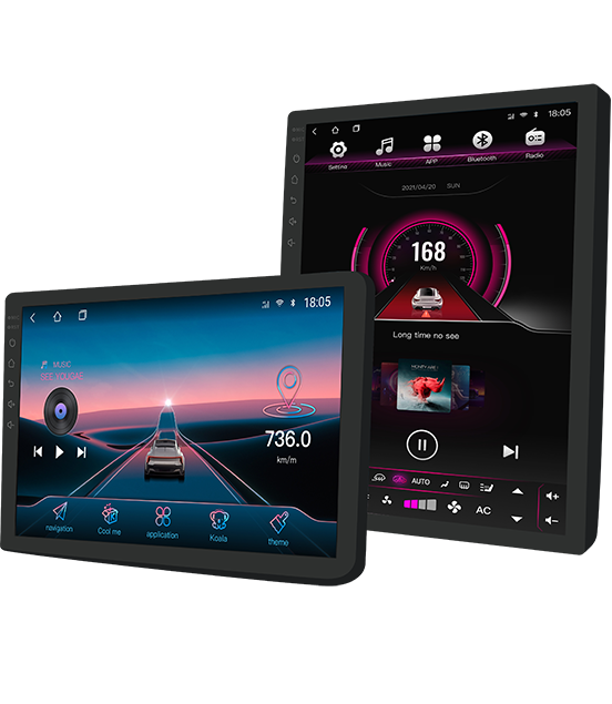
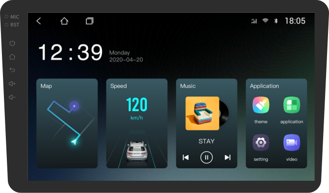
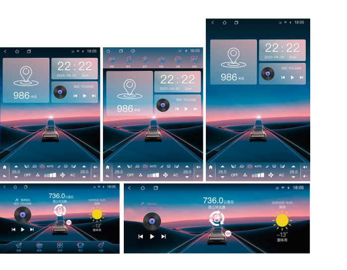
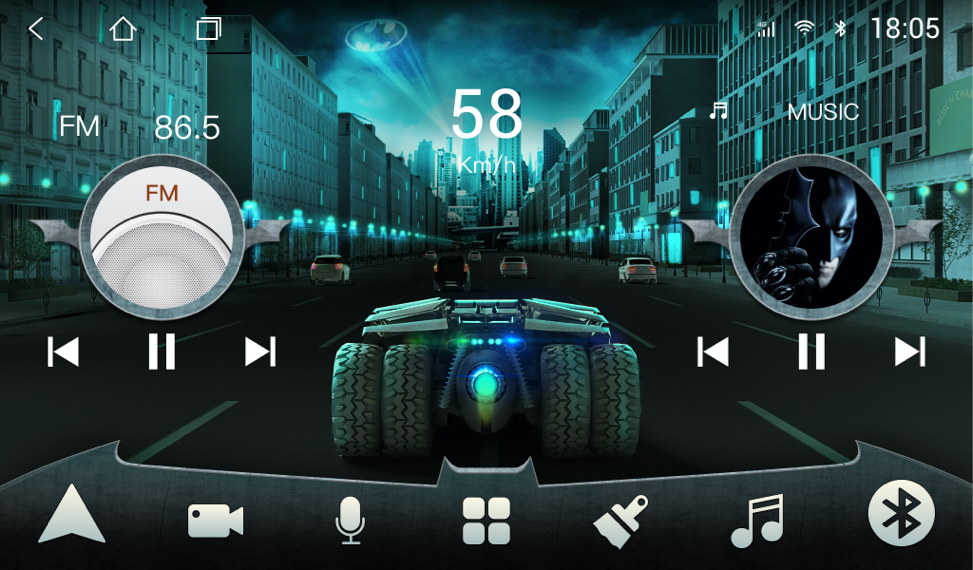
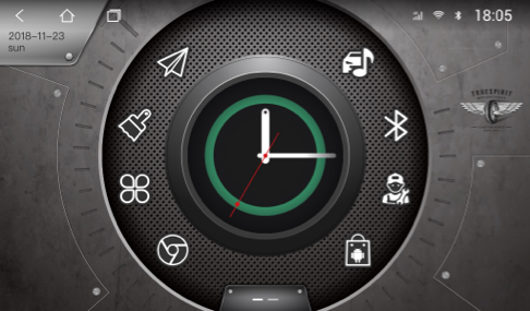
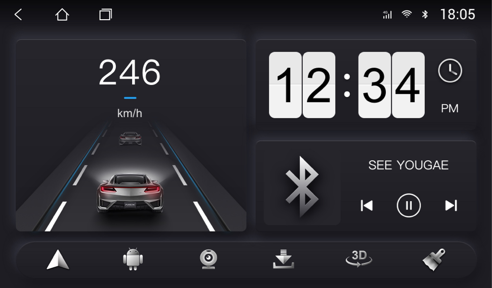
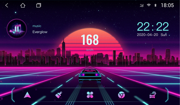
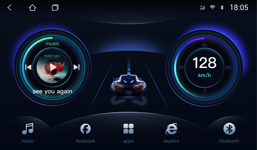
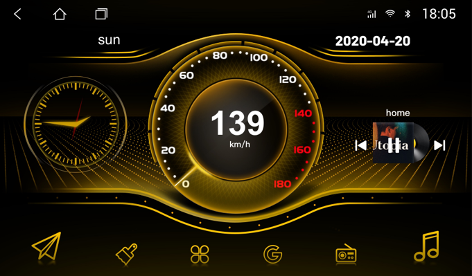
Not limited to a single theme framework, create 9 types of themes with different styles, there is always one that suits your taste!
Of course it's more than just looking good! When you drive on the road, you will find that the theme has rich dynamic effects, such as driving, instrumentation, ADAS, weather, etc., is it very interesting?
The shortcut icons on the desktop can be customized in style and function, and operate in the way you are used to!

product description
product description
Currently suitable resolutions are as follows:
Landscape contains: 1024x600、1024x768、1280x800、1280x480、2000x1200
Vertical screen includes: 768x1024、800x1280、1080x1920
If your car is different, it will use close resolution by default
Cars of Dingwei solution can use all the functions of the theme software, but some of the functions of cars of other solution providers are not available.

In addition to a single purchase, you can also
When engineers refer to the schematic top of the LAD402P, they mean two things:
If you need the IC’s top-view pinout (for LAD402P as a chip), here’s the typical configuration (assuming a 12-pin SIP or Multiwatt package):
Top view (pins facing down, text readable):
Pin 1  – Vref / Logic GND
Pin 2  – Phase A input
Pin 3  – Enable A
Pin 4  – Output A1
Pin 5  – Power GND
Pin 6  – Output A2
Pin 7  – VBB (motor supply)
Pin 8  – Output B2
Pin 9  – Power GND
Pin 10 – Output B1
Pin 11 – Enable B
Pin 12 – Phase B input
Note: Pin numbering may vary – always check the official datasheet. lad402p schematic top
Gather a multimeter (diode mode/resistance), a 24V DC or 110V AC test supply (optional), and a small screwdriver.
Use one NO contact to energize a pilot light when the contactor pulls in.
To appreciate the LAD402P schematic top, compare it to similar models: When engineers refer to the schematic top of
| Model | Contact Config | Top Schematic Difference | |-------|----------------|--------------------------| | LAD402P | 2 NO + 2 NC | Standard simultaneous action | | LAD4P2 | 1 NO + 1 NC (early make) | NO closes 2ms before NC opens | | LAD4P3 | 1 NO + 1 NC (late break) | NC opens 2ms before NO closes | | LAD401P | 1 NO + 1 NC | Only one set of contacts physically smaller | | LAD4P4 | 4 NO | All contacts NO — used for purely sealing circuits |
If your top schematic requires sequential behavior, the LAD402P is not the correct choice. Use LAD4P2 or LAD4P3.
The LAD402P is typically a dual H-bridge motor driver IC (often associated with SGS-Thomson / STMicroelectronics or similar older lines). It is used in stepper motor drivers and DC motor control applications.
However, if you’re referring to a PCB schematic labeled “LAD402P” from a specific device (e.g., a printer, CNC driver board, or industrial controller), that would be a custom board design. Note: Pin numbering may vary – always check
This is a break-before-make action, identical to a standard relay but optimized for motor inrush currents.
The lad402p schematic top is more than just a drawing; it’s the functional fingerprint of an industrial workhorse. Whether you are wiring a simple motor start-stop station or a complex safety interlock, understanding the physical terminal layout, the mechanical actuation, and the NO/NC transition logic is essential.
By memorizing the state table (coil off → NC closed, NO open; coil on → opposite) and practicing the manual actuation test, you can quickly diagnose 90% of field failures without any specialized tools.
Keep a copy of this guide near your control panel, and treat the LAD402P as a reliable partner — one that will faithfully follow its schematic top for millions of cycles, provided it is wired correctly and protected from overloads.
Need further help? Leave a comment below with your specific control circuit issue involving the LAD402P.
Weekly update

Please contact us
In addition to these FAQs, if you have more questions, youcan join our community by Telegram: https://t.me/carmateapp